


 النبات
 الحيوان
 الأحياء المجهرية
 علم الأمراض
 التقانة الإحيائية
 التقنية الحيوية المكروبية
 التقنية الحياتية النانوية
 علم الأجنة
 الأحياء الجزيئي
 علم وظائف الأعضاء
 الغدد
الغدد
 المضادات الحيوية
|
Read More
Date: 18-4-2016
Date: 19-4-2016
Date: 18-4-2016
|
Equipment required for low pressure liquid chromatography
1. The column
A sine qua non for column chromatography is the column. Basically this consists of a glass tube with adapters - preferably at either end - to spread the liquid flow from the thin bore input tubing out to the relatively large bore of the column and back in to the thin bore of the output tubing (Fig. 1). The column packing is supported on a sieve of some sort and a key element in the efficiency of the column is the “dead” volume between this sieve and the output tubing, which should be as small as possible. The purpose of the column is to effect a separation of different types of solute molecules and the whole purpose is defeated if the separated molecules arc allowed to remix, due to the dead volume being too large.
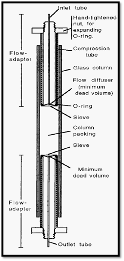
Figure 1. Schematic cross-section of a chromatography column.
Moveable flow-adapters enable different column bed volumes to be used. It is useful to have such flow adapters on both ends of the column. After packing and equilibration of the column bed, the adapter on the inlet side can be adjusted to be in contact with the upper surface of the packed resin bed. This is advantageous in that it facilitates sample application, as the sample can be simply introduced through the inlet tubing. It is also necessary if any form of gradient elution is to be used. In the absence of an upper flow adapter, the incoming buffer will mix in the dead volume above the packed resin bed and it will be impossible to get smooth, reproducible, gradient conditions.
The ratio between the internal diameter (i.d.) of the column and its length, the so-called “aspect ratio”, differs depending upon the application of the column. Generally, where adsorption occurs, such as in ion-exchange or affinity chromatography, columns with an aspect ratio of ca1:10 or less are used, whereas for molecular exclusion chromatography aspect ratios of about 1:50 are used.
Low pressure liquid chromatography columns typically consist of a uniform bore, thick walled, glass tube, with plastic adapters etc. Glass is favoured because it is chemically stable, transparent, and has good thermal conductivity. Obviously, all materials used to make columns must be chemically stable to buffers etc. and must not react with sample proteins. Proteins do adsorb to glass to some extent and this can be prevented by salinizing the column before use, though this is only warranted for the most critical work.
2. Moving the mobile phase
The chromatographic process requires movement of the mobile phase and the simplest way of effecting this is by siphoning the buffer from a reservoir which is elevated above the end of the outlet tube from the column (Fig. 2).

Figure 2. Simple chromatography, using a siphon to generate the mobile-phase flow.
The difference in potential energy (height) between the surface of the liquid in the buffer reservoir and the end of the outlet tube constitutes the “pressure head” which will cause the mobile phase to flow. A problem with this simple set-up is that, as the level of liquid in the reservoir drops, the pressure head will get smaller and the flow rate will decline. To keep the pressure head constant a so-called Marriott flask may be used (Fig. 3).
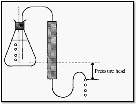
Figure 3. Use of a Mariette flask to maintain a constant pressure head.
Low-pressure column chromatography occurs at a somewhat leisurely pace and it is too tedious to attend to the column the whole time it is running. On the other hand, using the simple set-ups shown in Figs 2 and 3, there is a danger that an unattended column might exhaust the buffer supply and run dry. If this happens it becomes necessary to remove the resin and repack the column, which is tedious. Gravity-flow columns can be protected against running dry by arranging the inlet tubing to loop down below the outlet from the outlet tubing (Fig. 4).
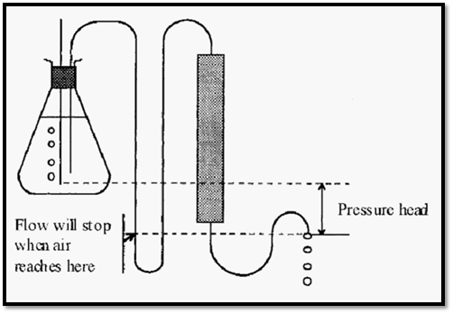
Figure 4. A run-dry protection loop on a gravity-flow column.
Note that gravity-flow columns can be operated with the flow going either downwards (Figs 56----58) or upwards through the column (Fig 5). An advantage of upward flow is that it is easier to arrange the system so that it will not run dry. Upwards flow is recommended with very soft gels, such as Sephadex G-200, which otherwise tend to be crushed by the combined effects of gravity and the buffer flow. With ascending flow, the flow supports some of the weight of the gel.

Figure 5. Ascending flow, with run-dry protection, and a tap for sample application.
With a gravity flow system the sample is most easily applied using a three-way tap on the inlet side of the column, as shown in Fig. 5. Better than a Marriotte flask, if the budget allows, is a peristaltic pump. “Peristalsis” refers to the rhythmic, wave-like, contractions that pump the gut contents along the digestive tract. By analogy, a peristaltic pump is one in which a flexible silicone tube is pinched by a roller which runs along the tube, pumping the tube contents in the same direction as it does so (Fig. 6). A peristaltic pump gives a smooth, almost pulse-free, flow.
The advantage in using a pump is that it gives more precise flow control and greater freedom in the chromatography lay-out, i.e. the buffer reservoir does not have to be higher than the column outlet. To prevent the column running dry during unattended operation when using a peristaltic pump, a timer switch is required. The timer can be arranged to switch off the pump - and any other associated apparatus - after a pre-set time. Note that because the peristaltic pump rollers pinch the silicone tube, there can be no flow of liquid through the pump when it is switched off.

Figure 6. Schematic drawing of a peristaltic pump.
When using a peristaltic pump, the sample can be applied simply by stopping the pump, transferring the inlet tubing from the buffer reservoir to the sample container, restarting the pump until all of the sample is sucked up, wiping the tubing and returning it to the buffer reservoir.
3 .Monitoring the effluent and collecting fractions.
The purpose of column chromatography is to separate solute molecules and it follows that some means is required of monitoring the separation achieved, and of separately collecting the resolved solute molecules. The separated fractions are most easily collected using an automatic fraction collector. Fraction collectors are available in different versions that collect the effluent stream in fractions on the basis of time, volume, or number of drops. Time-based fraction collectors are the simplest and most economical and, if the mobile phase flow rate is accurately controlled with a pump, the fractions collected will be of equal volume.
The simplest means of monitoring the separation of proteins is to collect the column effluent for the whole run in a convenient number of fractions - say, 100 - and to measure the A280 of each fraction in a spectrophotometer. The results can be used to construct a so-called elution profile, in which A280 is plotted against the elution volume. Such manual reading of the elution profile is inexpensive in capital terms, but it consumes operator time and, perhaps more importantly, some detailed information is lost. A better way, again if the budget can afford it, is to use a flow-through UV-monitor, that continuously reads the absorbance of the effluent stream at 280 nm. Such a monitor is plumbed into the effluent line, between the column and the fraction collector. Besides a power source, it requires two other electrical connections; an output to a recorder and an event-marker connection between the fraction collector and the recorder. Each time the faction collector changes tubes, it sends a pulse to the recorder so that the event - the tube change - is recorded. In this way it becomes possible to subsequently correlate the recorder trace of A280 with the collected fractions, so that fractions corresponding to the required peaks can be harvested. A flow-through UV-monitor constitutes a time-saving automatic system which also captures the fine detail of the elution profile.

Figure 7. A typical elution profile of A280 vs elution volume with event marker pulses.
4. Refrigeration
Proteins are structurally labile and are susceptible to microbial degradation. For these reasons, wherever possible, protein solutions are maintained at low temperature and preservatives are added to the buffers. Denaturation and degradation are both minimized by keeping the proteins cold and protein separations are therefore usually carried out at about 4C.
Chromatography is usually done in coldrooms, but working in coldrooms is miserable and unhealthy. A better and more versatile system is to have a refrigerated cabinet with some components of the chromatography set-up being kept at 4C and others at room temperature (Fig. 8). In Fig. 8, items labelled on the left are within the cabinet at 4C and those labelled on the right are at room temperature.
Electrical apparatus kept in a coldroom or fridge can be damaged by condensation of moisture onto its circuits. For this reason it is best to keep as much as possible at room temperature. The fraction collector must, however, be kept in the fridge.
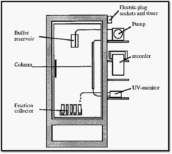
Figure 8. A protein chromatography system in a glass-fronted, refrigerated cabinet.
Remember if any electrical item is ever removed from the fridge for servicing, it must be allowed to warm up to room temperature and all moisture must be allowed to dry off before it is switched on. If this is not done, short-circuits caused by condensed moisture may burn out the electronics.
References
-Dennison, C. (2002). A guide to protein isolation . School of Molecular mid Cellular Biosciences, University of Natal . Kluwer Academic Publishers new york, Boston, Dordrecht, London, Moscow .


|
|
|
|
لخفض ضغط الدم.. دراسة تحدد "تمارين مهمة"
|
|
|
|
|
|
|
طال انتظارها.. ميزة جديدة من "واتساب" تعزز الخصوصية
|
|
|
|
|
|
|
جامعة سومر: حفل تخرج طلبة الجامعات يسهم بتنمية الروح الوطنية ويشجع على المثابرة والاجتهاد
|
|
|