


 الفيزياء الكلاسيكية
 الكهربائية والمغناطيسية
 علم البصريات
 الفيزياء الحديثة
 النظرية النسبية
 الفيزياء النووية
 فيزياء الحالة الصلبة
 الليزر
 علم الفلك
 المجموعة الشمسية
 الطاقة البديلة
 الفيزياء والعلوم الأخرى
 مواضيع عامة في الفيزياء
|
Read More
Date: 8-3-2016
Date: 22-5-2016
Date: 20-3-2016
|
ELECTROOPTIC MODULATORS
Electrooptic modulators rely on the phenomenon of birefringence, as induced in a crystal by the application of an external electric field. Birefringence is an effect exhibited in certain crystalline materials in which an incident light ray will separate into two rays that may travel in different directions, the direction traveled being dependent on that ray’s polarization. For each of the two rectangular states of polarization (perpendicular and parallel), the light will travel in a different direction as it exits the crystal. This effect is also called double refraction, since light entering the crystal is refracted into two different directions. Calcite is a natural crystal that exhibits birefringence. This crystal will separate an incident beam of light into two beams with different polarizations.
Figure 1.1 shows the effect of birefringence on a beam of unpolarized light that is incident on the surface of a briefringent crystal at an angle θ. The two different components of polarization (perpendicular and parallel) take two separate paths through the crystal. This effect is caused by the index of refraction of the crystal, which has the property of being dependent on the polarization of the incident beam. For such a crystal, two indexes of refraction exist, one for each polarization of the incident light. Having different indexes of refraction, each polarization of
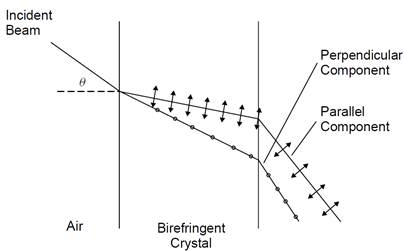
Figure 1.1. Birefringence.
light is refracted at a different angle inside the crystal. In the case of calcite, the indexes of refraction are 1.66 for light in the perpendicular plane and 1.49 for light in the parallel plane. Knowing the index of refraction for each component, the behavior of this component in the crystal may be determined using Snell’s law.
There are also a number of crystals that exhibit birefringence only when an external electric field is applied. This phenomenon, called the electrooptic effect, may be used in the case of a Q-switch to block an intracavity light beam. It may also be used to deflect beams. An electrooptic modulator is shown schematically in Figure 1.2. Incident light is polarized and then passed through the electrooptic material (this polarization is not needed if the incident light is already polarized). Light exiting the crystal is passed through a second polarizing filter, called an analyzer. Since the crystal causes no change to the light passing through it when not energized, the analyzer, oriented at 90o to the polarizer, prevents any light from being transmitted through the device. In essence, when the crystal is not energized, the device acts as a shutter. When an external electric field is applied to the crystal, the direction of the polarization of light passing through it is rotated by 90o. Then the light will pass through the analyzer; effectively the shutter is open.
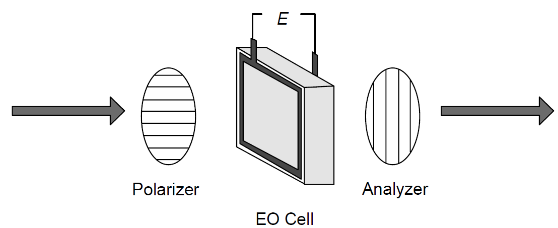
Figure 1.2. Electrooptic modulator.
In amodulator, the two components (with different polarizations) travel through the crystal in the same direction; they do not separate from one another. However, the relative phase of each component changes. Since the index of refraction is different for each polarization, they race through the crystal at different velocities and so emerge from the crystal with different phases. As they continue through the crystal, the phase difference increases. This depends on the thickness of the crystal as well as on the electric field applied. When the beams emerge from the crystal, the polarization of the combined single beam depends on the accumulated phase difference between the two individual polarized components. A phase difference of one-half wavelength results in the overall polarization of the beam being rotated by 908 from its original direction. When this polarization of light falls on the analyzer, it passes through.
Two electrooptic effects are possible, classified according to how the refractive index changes relative to the applied electric field: the Pockels effect and the Kerr effect. Which effect occurs depends on the material involved. In the Pockels effect the change in refractive index is a linear function of an applied electric field E:
 (1.1)
(1.1)
where a1 is the linear electrooptic coefficient. The coefficient a1 is a property of a material and is zero in any non-crystalline substance, so Pockels EO modulators are always constructed using a crystal, such as those listed in Table 1.1, which also details the range of index of refraction possible for each polarization of light.
The other electrooptic effect, in which the change in refractive index is a function of the square of the applied electric field, is the Kerr effect, in which the change of refractive index is described by
 (1.2)
(1.2)
where a2 is a second-order electrooptic coefficient, or, more generally as
 (1.3)
(1.3)
where K is the Kerr coefficient, a property of a particular material. All materials exhibit the Kerr effect, although the effect is very small in many materials, so an extremely high electric field may be required to observe the effect. This may not always be physically possible since dielectric breakdown will occur in any material
TABLE 1.1. Common Pockels Cell EO Materials

when too high a voltage is applied. Common materials used for Kerr-type EO modulators include the liquid nitrobenzene (which is toxic) and glass. Kerr-type modulators are uncommon in laser use, and essentially all modern modulators use the Pockels effect. These are often called Pockels cell modulators.
In a practical EO modulator an electrooptic crystal (ADP or KDP in this example) is sandwiched between two electrodes. The crystal is then inserted between a pair of crossed polarizing filters in Figure 1.2. By applying an external electric field in the form of a direct-current potential of several thousand volts across the crystal (parallel to the optical axis of the crystal), the refraction of the crystal itself changes. The electric field E (in units of V/m) can be found simply by dividing the applied voltage by the thickness of the cell (the distance over which the voltage is applied).
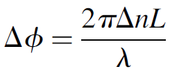
The phase change for light passing through a modulator is proportional to the thickness of the EO material as well as the change in refractive index generated by the electric field according to
 (1.4)
(1.4)
which allows us to express the transmission of the modulator (T) according to the change in refractive index according to
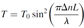 (1.5)
(1.5)
where T is the transmission, T0 the maximum transmission of the assembly when open, Δn the difference in refractive index for the two polarizations, L the length of the crystal, and λ the wavelength of the light. The birefringence is a function of the applied electric field and hence the voltage applied to the crystal. Mathematically, it can be shown that the maximum transmission occurs when the term πΔnL/λ = π/2 or when
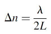 (1.6)
(1.6)
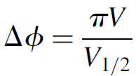
This occurs at a voltage called the half-wave voltage, denoted V1/2. The half-wave voltage is a property of the material itself, but this voltage increases with the wavelength according to
 (1.7)
(1.7)
EO modulators operating in the infrared thus require much higher voltages than those operating in the visible region (which often operate at voltages of 5 to 10 kV). This factor can limit the use of EO modulators in infrared lasers (such as a CO2 laser operating at 10.6 μm).
Example 1.1. Pockels Cell Voltage Consider a Pockels cell in which the phase shift is given by equation (1.4):
We can substitute for Δn in terms of the half-wave voltage so that in terms of applied voltage the phase shift becomes
Now, by substituting for Δϕ in equation (1.5), the relationship of transmission to applied voltage becomes
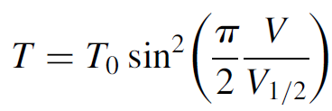
Hence by applying a variable voltage to the cell, we can modulate the transmission to any value desired. Such techniques have been used to transmit high-speed signals such as video via a laser beam.
Electrooptic modulators are the fastest form of Q-switches for lasers and feature switching times of less than 10 ns. They are very repeatable and have a large hold-off or extinction ratio. This is the ratio of light passing through the modulator when it is on (open) to when it is off (blocked). For an EO modulator this ratio can be as high as 1000 : 1, which translates into a huge insertion loss when used as a Q-switch inside a laser cavity. In the blocked state the Q of the laser cavity will be extremely slow. The EO modulator is so fast that it is often used as a shutter for ultrafast cameras: for example, those used to photograph atomic bomb blasts. Unfortunately, suitable electrooptic crystals are very expensive, and the electrical driver circuitry, which must produce a high-voltage pulse with a rise time in the nanosecond range, is also critical. Circuitry to drive an EO modulator usually consists of a high-voltage capacitor discharged quickly through the modulator using a thyratron (a high-speed switch). Still, when a Q-switched laser is required with nanosecond pulse times (e.g., a double-pulse ruby laser used for fast holography) an EO modulator (usually, a Pockels cell) is the only option. For less time-critical applications, a less expensive (and simpler) alternative is a modulator based on the interaction of sound with light, although this approach does not yield the performance of an EO switch.


|
|
|
|
لخفض ضغط الدم.. دراسة تحدد "تمارين مهمة"
|
|
|
|
|
|
|
طال انتظارها.. ميزة جديدة من "واتساب" تعزز الخصوصية
|
|
|
|
|
|
|
عوائل الشهداء: العتبة العباسية المقدسة سبّاقة في استذكار شهداء العراق عبر فعالياتها وأنشطتها المختلفة
|
|
|