Parabolic dishes
 المؤلف:
A. Roy, D. Clarke
 المصدر:
Astronomy - Principles and Practice 4th ed
 الجزء والصفحة:
p 361
 31-8-2020
 2265
2265
Parabolic dishes
Directional antennas such as the Yagi antenna and the two-dimensional array all suffer from the disadvantage that the wavelengths that they can monitor are at once fixed by the choice in the size of the half-wave dipoles. A more versatile system is that which uses a large parabolic collecting dish, bringing the collected radiation to a focus where a dipole or collecting horn and waveguide system is placed. A range of dipoles and horns can be made available according to the wavelengths that are to be investigated. To obtain even a modest angular resolution, the collecting dish must be at least several wavelengths in diameter. By applying the formula for the resolution of a telescope , it can readily be shown that, in order to be able to resolve an angle of 7◦, the ratio of the diameter of the

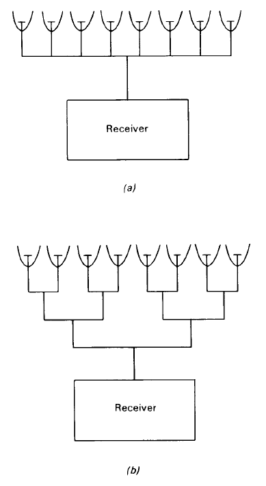
Figure 1. An eight-element interferometer as (a) a collinear array and (b) in the Christiansen arrangement.
dish to the observing wavelength must be of the order of at least ten to one. Higher angular resolution at the same wavelength would require an even larger collecting area and it is for this reason that radio telescope dishes run in size from a few metres to a few hundred metres. The world’s largest steerable dish telescope is the 100 m National Radio Astronomy Observatory (USA) sited at Green Bank, West Virginia. Referred to as the Green Bank Telescope, or GBTW 21.2, it was commissioned in 2000. The non-steerable radio telescope at Arecibo, Puerto Rico, is approximately 300 m in diameter and is a terra-formed structure.
A typical collecting dish has a small focal ratio. This allows the receiving antenna to be at not too great a distance above the bowl and the reflecting surface which collects the radio radiation then acts as a shield against locally generated signals and interference. The actual reflecting surface need not be made of metal plate; it can be constructed from wire mesh in which the size of the holes determines the lower limit of the wavelength which can be observed effectively. The contours of the parabolic dish must also be made to an accuracy of about one-eighth of the smallest wavelength to be observed if the telescope is not to lose its potential angular resolution.
The absolute power gain of a radio telescope dish is given by inserting the value of the geometric
aperture. This value is approximately the same as that of a two-dimensional array

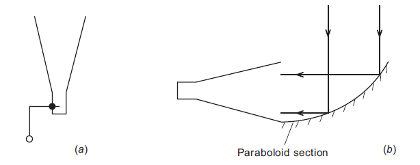
Figure 2. (a) A horn antenna with feed output. (b) A horn antenna with a reflection collector.
of antennas covering the same area. However, the calculation of power gain usually requires an adjustment to allow for the fact that the feed horn (see later) is designed to prevent ‘spill-over’ to the ground with the result that the dish is effectively under illuminated. A typical loss is of the order of a factor of two so that Ae ≈ A/2, where A is the full geometric area of the dish. If the absolute power gain is expressed in terms of the diameter of the dish, it is given by
 (1)
(1)
Thus, if a 10 m dish is used at a wavelength of 1 m, the absolute power gain is close to 103.
As with the case of optical telescopes, some radio dishes are constructed to support a secondary reflector prior to the primary focus, so operating as a Cassegrain system. With this configuration, the position of the feed is more accessible being just behind the dish and the system’s length is reduced.
 الاكثر قراءة في مواضيع عامة في علم الفلك
 اخر الاخبار
اخبار العتبة العباسية المقدسة


