


 الفيزياء الكلاسيكية
 الكهربائية والمغناطيسية
 علم البصريات
 الفيزياء الحديثة
 النظرية النسبية
 الفيزياء النووية
 فيزياء الحالة الصلبة
 الليزر
 علم الفلك
 المجموعة الشمسية
 الطاقة البديلة
 الفيزياء والعلوم الأخرى
 مواضيع عامة في الفيزياء
|
Read More
Date: 24-3-2016
Date: 25-3-2016
Date: 27-3-2016
|
EXCIMER LASER STRUCTURE
Excimer lasers resemble TEA lasers in that they feature two long, transverse electrodes and the gas pressures are at atmospheric pressures or greater (most excimer lasers operate at many times atmospheric pressure). Unlike the nitrogen TEA laser, the lifetime of the ULL is on the order of tens of nanoseconds, so the requirements for a low inductance (and hence fast) electrical discharge path are somewhat relaxed (although by no means trivial). Most excimer lasers use a discharge circuit consisting of a single large capacitor and a low-inductance thyratron switch, as outlined in Figure 1.1.
The main capacitor (C1) charges with high voltage of about 40 kV through the charging resistor and the charging inductor. To fire the laser, the thyratron is triggered, shorting the left side of C1 to ground. Current then flows from capacitor C1 through the laser tube, where the discharge occurs. This discharge occurs very
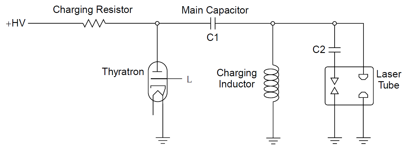
Figure 1.1. Excimer laser discharge circuitry.
rapidly, on the order of around 40 ns, so the charging inductor is essentially an open circuit during the rapid discharge. Essential components of the excimer laser high voltage section are annotated in Figure 1.2. The capacitor is the large white block and is connected to the thyratron via a thick copper tube.
Current flowing from the capacitor flows into the laser tube but discharge does not occur immediately since the pressure of the laser tube is high (many atmospheres) and gas inside the laser channel is not yet ionized. Ionization is performed by current flowing through small capacitors C2 and jumping small preionization spark gaps inside the laser tube immediately adjacent to the main laser discharge channel. UV radiation produced from these sparks ionizes gas in the laser channel, which then conducts the main discharge current, producing a laser pulse. A photograph of the laser channel is shown in Figure 1.3. The white cylinders on either

Figure 1.2. Excimer laser high-voltage section.
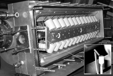
Figure 1.3. Excimer laser discharge channel with preionizer.

Figure 1.4. Excimer laser heat removal mechanism and gas flow.
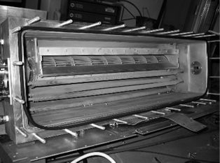
Figure 1.5. Excimer laser heat exchanger and fan.
side of the laser discharge channel are the preionization capacitors (C2) which are inside the actual laser housing. A detail in the right corner of the figure shows a single preionization spark gap. There are two rows of 13 in this laser, one row on either side of the laser channel. It is evident that the preionization gaps are much smaller than the gap for the laser channel, ensuring that these gaps fire despite the high pressure in the tube.
Heat removal from the discharge is a major issue with an excimer laser. Given that the input energy to the tube is several kilowatts, there is a large amount of heat that must be extracted from the high-pressure lasing gas. This is accomplished by using a large squirrel-cage blower and water-cooled heat exchanger tubes within the laser vessel itself. Laser gases are forced around the vessel at high speeds: through the lasing channel and passing through water-cooled coils where the gas is cooled and recirculated through the laser. The heat-removal mechanism is diagrammed schematically in Figure 1.4 and shown in Figure 1.5, where the laser channel and capacitors visible in Figure 1.3 have been removed to reveal the blower and heat-exchanging tubes (four of them in this case).

|
|
|
|
دخلت غرفة فنسيت ماذا تريد من داخلها.. خبير يفسر الحالة
|
|
|
|
|
|
|
ثورة طبية.. ابتكار أصغر جهاز لتنظيم ضربات القلب في العالم
|
|
|
|
|
|
|
قسم شؤون المعارف ووفد من جامعة البصرة يبحثان سبل تعزيز التعاون المشترك
|
|
|