Until now we have concentrated primarily upon circuits in which all relays or switches were assumed to operate simultaneously. We have disregarded the time interval between the closing of a relay control path and the closing of the relay contacts, called the operate time of the relay; similarly, we have ignored the release time of a relay, that is, the delay between the opening of the control circuit and the opening of the relay contacts. This idealization has simplified the problem of design of relay circuits, and in many applications these delays are of no serious consequence. Often, however, these time delays cannot be ignored, and sometimes the delays that cause relays to operate in sequence, rather than simultaneously, can be used to ad-
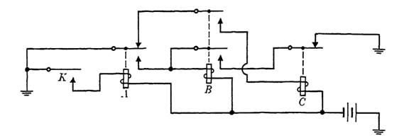
FIG. 1-1. A sequential circuit.
vantage to perform tasks that would be impossible otherwise. In many applications, a timing device for introducing sequential signals is an essential part of the design. In this section, we will consider some circuits that operate sequentially and charts for representing their operation. In the next section, we will discuss the design of such circuits.
A circuit in which time is important, and in which two or more things happen in sequence will be termed a sequential circuit. Such a circuit is shown in Fig. 1-1. In this diagram, if key K is depressed and held down momentarily, relay A is operated first. In operating, A closes the lead to ground on the winding of B, which causes B to operate, which locks B through a break contact on C. If now K is released, relay A releases, closing the control path of C. C, in operating, breaks the hold path on B, causing B to release, and this in turn releases C. The relays now will remain in released position until K is again depressed.
The operation of this sequential circuit can be summarized in a sequence diagram as in Fig. 1-2. The width of each column corresponds to the length of the operate or release time of the relay involved. It is often the case that the exact size of these time intervals is less important than the sequence of events to which they correspond. In Fig. 1-2, the interval in which each relay is operated is occupied by a horizontal line opposite the appropriate symbol for the relay. An empty interval is usually given on both ends of such a diagram if a state ever occurs in which all relays are released.

FIG. 1-2. Sequence chart for the circuit of Fig. 1-1.
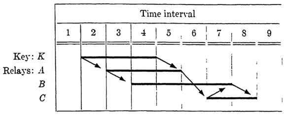
FIG. 1-3. Sequence chart for the circuit of Fig. 1-1, showing control.
To help to represent the action of the circuit, arrows are often drawn to indicate the immediate cause of each change of state of each relay. For example, in the circuit shown in Fig. 1-1, operation of K causes the operation of A, and release of A causes C to operate. The appropriate arrows for the sequence diagram of this circuit are shown in Fig. 1-3.
Figure 1-1 indeed illustrates a sequential circuit, but the circuit does not perform any function; that is, there is no indicated output. On the other hand, the circuit of Fig. 1-4 does have an output, in the form of a light which shines during the time that relay C is operated and A is released. This output could equally well be a signal to another part of the circuit, to be used for any of a number of purposes other than providing a light. Another feature of this circuit is that it automatically recycles itself; that is, it will go through the same sequence of states repeatedly until a part fails or the current supply is cut off.
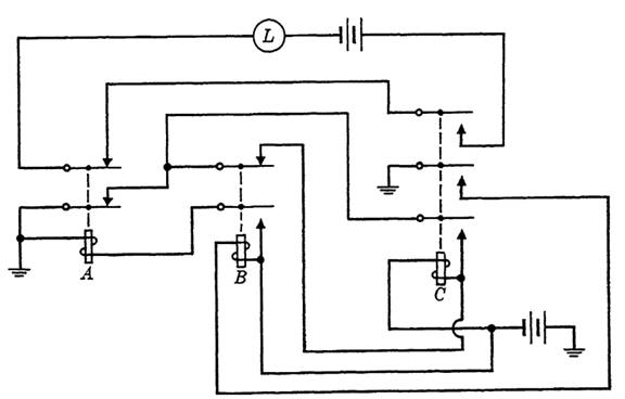
FIG. 1-3. An automatically recycling sequential circuit with output.

FIG. 1-4. Sequence diagram for the circuit of Fig. 1-3.
To construct the sequence diagram for this circuit, let us assume an initial state in which all relays are released. C is operated first, through breaks on A and B, and will be held until A operates. In operating, C closes the operate path of B. B, in operating, closes the operate path of A, causing A to operate, which in turn breaks the hold path on C. In releasing, C causes the release of B, which then causes A to release. Now with all relays released, C will again be operated, and the cycle is repeated as before. The output is wired through a make on C and a break on A, causing the light to shine during the required intervals. The sequence chart is given in Fig. 1-4.
It may happen in operating, or in releasing, that a particular relay simultaneously controls two other relays. Such a condition is termed a race condition and should be avoided in constructing sequential circuits if the sequence in which the two relays operate affects the remainder of the circuit. Where this cannot be avoided, two relays with significantly different operate (or release) times may be used.
In this section, we have considered sequential circuits in which the time intervals were determined primarily by operate and release times of the relays involved. In the next section, we will consider examples in which the inputs for the circuit are sequential. Actually, the first example of this section included one input of this type, the operation of the key K.


