تاريخ الرياضيات

الاعداد و نظريتها
تاريخ التحليل
تار يخ الجبر
الهندسة و التبلوجي
الرياضيات في الحضارات المختلفة
العربية
اليونانية
البابلية
الصينية
المايا
المصرية
الهندية
الرياضيات المتقطعة
المنطق
اسس الرياضيات
فلسفة الرياضيات
مواضيع عامة في المنطق
الجبر
الجبر الخطي
الجبر المجرد
الجبر البولياني
مواضيع عامة في الجبر
الضبابية
نظرية المجموعات
نظرية الزمر
نظرية الحلقات والحقول
نظرية الاعداد
نظرية الفئات
حساب المتجهات
المتتاليات-المتسلسلات
المصفوفات و نظريتها
المثلثات
الهندسة
الهندسة المستوية
الهندسة غير المستوية
مواضيع عامة في الهندسة
التفاضل و التكامل
المعادلات التفاضلية و التكاملية
معادلات تفاضلية
معادلات تكاملية
مواضيع عامة في المعادلات
التحليل
التحليل العددي
التحليل العقدي
التحليل الدالي
مواضيع عامة في التحليل
التحليل الحقيقي
التبلوجيا
نظرية الالعاب
الاحتمالات و الاحصاء
نظرية التحكم
بحوث العمليات
نظرية الكم
الشفرات
الرياضيات التطبيقية
نظريات ومبرهنات
علماء الرياضيات
500AD
500-1499
1000to1499
1500to1599
1600to1649
1650to1699
1700to1749
1750to1779
1780to1799
1800to1819
1820to1829
1830to1839
1840to1849
1850to1859
1860to1864
1865to1869
1870to1874
1875to1879
1880to1884
1885to1889
1890to1894
1895to1899
1900to1904
1905to1909
1910to1914
1915to1919
1920to1924
1925to1929
1930to1939
1940to the present
علماء الرياضيات
الرياضيات في العلوم الاخرى
بحوث و اطاريح جامعية
هل تعلم
طرائق التدريس
الرياضيات العامة
نظرية البيان

RELAY CIRCUITS AND CONTROL PROBLEMS-Basic relay control paths
 المؤلف:
J. ELDON WHITESITT
المؤلف:
J. ELDON WHITESITT
 المصدر:
BOOLEAN ALGEBRA AND ITS APPLICATIONS
المصدر:
BOOLEAN ALGEBRA AND ITS APPLICATIONS
 الجزء والصفحة:
106-109
الجزء والصفحة:
106-109
 3-1-2017
 1869
1869


+
-
20
Before we can attempt to design circuits using relays to meet given sets of requirements, it is necessary to consider the ways in which a relay can be operated or released by an open or closed circuit which we will term a control path. In general, a relay circuit will be an interconnection of relays involving three types of circuits or paths. The first type of circuit will be termed an input path, which is a circuit consisting of switches or relays operated manually or by outside current sources, sources perhaps in a separate part of the machine being constructed. This is the part of the circuit by which instructions are given to the system as a whole. The second type of circuit, termed an output path, will usually be a circuit involving contacts on relays internal to the system. This is the part of the circuit which performs the task for which the circuit is constructed. The third type of circuit, associated with a given relay internal to the system, is called a control path and operates or releases the given relay only. It is helpful to think of a relay circuit in terms of these types of paths even though there is often considerable overlapping between them. For instance, a given input condition consisting of a current source or the state of a manually operated switch may well be a direct part of the output path. Control paths may be composed entirely from parts of input paths, may depend entirely on output paths of subcircuits designed to operate the relay, or may depend in part on the output paths of the circuit as a whole. These basic paths will be illustrated in the examples of this section and will be discussed in more detail in later sections.
Figure 1-1 illustrates a direct control path for a relay X, with two equivalent circuits. In this diagram, the relay is operated when switch a is closed, and released when a is opened. Here we would consider the input
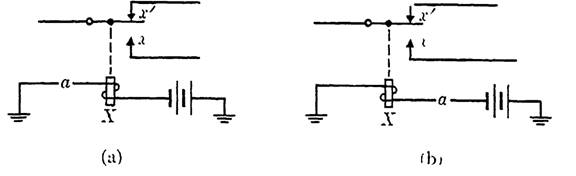
FIG. 1-1. Direct control path of relay X.
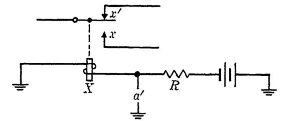
FIG. 1-2. Shunt control path.
condition to be the state of switch a. No input path is shown, but an input path is involved if switch a is a contact on a relay Y, say, in which case the control path for the relay Y would be the input path for the circuit shown. Output paths may be formed by using either of the contacts operated by relay X. We would designate these contacts as x for the make and x' for the break contact.
Figure 1-2 shows a control path for relay X equivalent to that of Fig. 1-1, but in which the relay operates when the switch a' is opened. It may be convenient to employ such a path, called a shunt path, if the input condition is such as to require operation of a relay upon the opening of a circuit. There are disadvantages in the shunt path since the current through the closed path is wasted, and the resistor R introduced to minimize this loss is an added expense. Also, the release time of the relay is lengthened by a shunt control path. Note that whenever the function representing the shunt path is the negative of that used in a direct control path, the operation conditions for the relay are identical.
Figure 1-3 shows a control path for a relay X in which the relay itself affects its own control path. Such a control path is called a locking circuit, and if switch b is closed (once a has been closed to cause initial operation
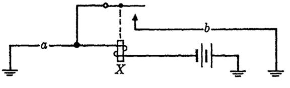
FIG. 1-3. Locking path.
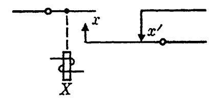
FIG. 1-4. Continuity transfer (make-break).
of X), the relay will remain operated until such a time as b is opened, regardless of the state of a. This is the basic "memory" device in a relay circuit, which allows a relay to maintain its operated state after the input condition causing operation has disappeared. In this figure, no output paths are shown but could he formed from other contacts operated by relay X. We can consider the control path for this relay as consisting partly of an input path (switch a), and partly of an output path (the contact on X), which illustrates the fact pointed out earlier that there is no clear-cut division of a circuit into input, output, and control paths.
In a transfer contact, it is sometimes important that the make contact be closed prior to the opening of the break contact. Such a transfer can be constructed, and is called a continuity transfer (or a make-break contact). It is sufficient for our purposes to know that such a transfer can be built; for the interested reader, we indicate the method of construction in the diagram convention given in Fig. 1-4. Other special devices, involving several break and make contacts, are available to operate the contacts in a variety of orders.
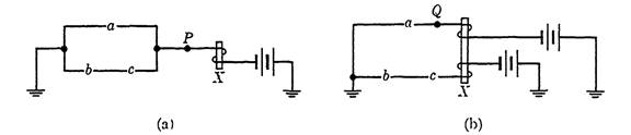
FIG. 1-5. Relay operated by a + be.
Several variations in these basic control paths are possible, and some will be introduced later when needed. Other arrangements of contacts may be more suitable than these for special purposes, but these illustrate the basic notions of relay control and operation.
One more control path will be shown to illustrate some additional possibilities in a control circuit. First, suppose that a control path is to be designed in such a way that a relay X operates if switch a is closed or if both switches b and c are closed. A suitable control circuit is shown in Fig. 1-5(a). Suppose that it is desired to use switch a in another part of the circuit as well. If point P were to be connected to another circuit, the desired lead to ground would be formed if a were closed, but a lead to ground would also be formed if b and c were both closed. To avoid this difficulty, a doubly wound relay might be used to isolate a from be, as shown in Fig. 1-5(b): A lead from point Q may be used to include a in another part of the circuit.
When a manually operated switch is used in a circuit, it will be convenient to distinguish between two types of switches. The first, which we will continue to refer to simply as a switch, will be so designed that it can be left in either open or closed position. The second, which we will refer to as a key, will be thought of as a switch subject to a spring that may be manually depressed to change the state of one or more contacts on the key, but which will automatically return to its initial position when released. That is, a key will work exactly like a relay except that it is operated manually rather than by an electromagnet.
EXAMPLE 1. A circuit A has been constructed to realize a certain function f. It is now desired to realize f'. Show how A may be used to obtain the desired circuit. Ignore the operate and release time for the relay used.
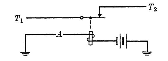
FIGURE 1-6
Solution. Since f' is a function which is 0 when f is 1 and conversely, the function f12 in Fig. 5-8 is clearly equal to f', since the path from T1 to T2 is closed when A is open (relay released) and open when A is closed (relay operated).
EXAMPLE 2. A relay X is to be operated when either of two switches y and z is closed, but not when both y and z are closed. Once operated, the relay is to remain in operation until a key K is depressed, at which time it is to release, regardless of the states of switches y and z.
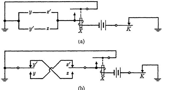
FIGURE 1-7
Solution. Referring to Fig. 1-3, a in the diagram must be replaced by a circuit which realizes the function f = yz' + y'z to satisfy the requirements for initial operation. Now a locking path is needed, as in Fig. 1-3, but if key K were inserted in place of b, the relay would not release at any time when f had the value 1. K will cause the release of the relay under any circumstances if it is introduced as indicated in Fig. 1-7(a). Figure 1-7(b) is equivalent to Fig. 1-7(a), but uses a different notation for the switches y and z.
 الاكثر قراءة في الجبر البولياني
 اخر الاخبار
اخبار العتبة العباسية المقدسة

الآخبار الصحية


مواضيع ذات صلة
 قسم الشؤون الفكرية يصدر كتاباً يوثق تاريخ السدانة في العتبة العباسية المقدسة
 "المهمة".. إصدار قصصي يوثّق القصص الفائزة في مسابقة فتوى الدفاع المقدسة للقصة القصيرة
 (نوافذ).. إصدار أدبي يوثق القصص الفائزة في مسابقة الإمام العسكري (عليه السلام)