تاريخ الرياضيات

الاعداد و نظريتها
تاريخ التحليل
تار يخ الجبر
الهندسة و التبلوجي
الرياضيات في الحضارات المختلفة
العربية
اليونانية
البابلية
الصينية
المايا
المصرية
الهندية
الرياضيات المتقطعة
المنطق
اسس الرياضيات
فلسفة الرياضيات
مواضيع عامة في المنطق
الجبر
الجبر الخطي
الجبر المجرد
الجبر البولياني
مواضيع عامة في الجبر
الضبابية
نظرية المجموعات
نظرية الزمر
نظرية الحلقات والحقول
نظرية الاعداد
نظرية الفئات
حساب المتجهات
المتتاليات-المتسلسلات
المصفوفات و نظريتها
المثلثات
الهندسة
الهندسة المستوية
الهندسة غير المستوية
مواضيع عامة في الهندسة
التفاضل و التكامل
المعادلات التفاضلية و التكاملية
معادلات تفاضلية
معادلات تكاملية
مواضيع عامة في المعادلات
التحليل
التحليل العددي
التحليل العقدي
التحليل الدالي
مواضيع عامة في التحليل
التحليل الحقيقي
التبلوجيا
نظرية الالعاب
الاحتمالات و الاحصاء
نظرية التحكم
بحوث العمليات
نظرية الكم
الشفرات
الرياضيات التطبيقية
نظريات ومبرهنات
علماء الرياضيات
500AD
500-1499
1000to1499
1500to1599
1600to1649
1650to1699
1700to1749
1750to1779
1780to1799
1800to1819
1820to1829
1830to1839
1840to1849
1850to1859
1860to1864
1865to1869
1870to1874
1875to1879
1880to1884
1885to1889
1890to1894
1895to1899
1900to1904
1905to1909
1910to1914
1915to1919
1920to1924
1925to1929
1930to1939
1940to the present
علماء الرياضيات
الرياضيات في العلوم الاخرى
بحوث و اطاريح جامعية
هل تعلم
طرائق التدريس
الرياضيات العامة
نظرية البيان

RELAY CIRCUITS AND CONTROL PROBLEMS-Introduction
 المؤلف:
J. ELDON WHITESITT
المؤلف:
J. ELDON WHITESITT
 المصدر:
BOOLEAN ALGEBRA AND ITS APPLICATIONS
المصدر:
BOOLEAN ALGEBRA AND ITS APPLICATIONS
 الجزء والصفحة:
104-106
الجزء والصفحة:
104-106
 3-1-2017
 1676
1676


+
-
20
In (SWITCHING ALGEBRA), we discussed switching circuits, and the type of switch used was thought of as a manually operated device that could be either open or closed. Although the material presented was equally applicable to circuits involving other bistable devices, many problems inherent in the type of device used were completely ignored. For instance, it was assumed possible to open one switch and close another simultaneously. Such idealizations are permissible in introducing a theory, but in an actual problem of design, considerably more care must be given to details of circuit operation. This is impossible without some discussion of the specific apparatus which is to be used. In this chapter, we will still be guilty of some disregard of details, but specific devices will be introduced to help minimize this shortcoming. In addition, the introduction of relays will allow us to design circuits with properties more complex and much more useful than would be possible if our circuits were limited to manually operated switches.
In certain parts of a circuit diagram, the type of switch used may be immaterial. We may even wish to use a manually operated switch. If such is the case, the notation of (SWITCHING ALGEBRA), may be used. In other cases, when the switch is to be operated by an electromagnet, a new notation will be introduced. Figure 1-1 illustrates this notation.
The term contact carries essentially the same meaning as switch, in that it is a device between two leads, which may be open or closed. However, we will think of a contact as a device consisting of (a) a spring, represented in the diagram as  when it is in rest position, to which one lead is connected, and (b) a point, represented in the diagram as ↑, to which the second lead is connected. By a make contact, we mean a contact that is open when the spring is at rest, and by a break contact, we mean one that is closed when the spring is at rest. A transfer contact is simply a combination of a make and a break contact operating from a single spring. In counting the number of contacts in a given circuit, a transfer contact will be counted as two contacts. Should it be possible to replace a separate make and break by a single transfer contact, we will consider this a simplification, since the second would usually be more economical to construct. For convenience, we will always use unprimed lower case italic letters, x, y, a, ... , to represent make contacts and primed letters, x', y', a', ... , to represent break contacts.
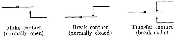
FIG. 1-1. Circuit diagram conventions.
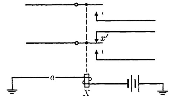
FIG. 1-2. Relay with control circuit. This relay operates a transfer contact and a make contact simultaneously.
A relay is a combination of a certain set of contacts all operated by a single electromagnet. When no current passes through the coil of the magnet, all contact springs are at rest: make contacts are open, and break contacts are closed. When there is current through the winding of the coil, the relay is activated, and the conditions are reversed. The relay itself will be denoted by a capital italic letter, say X, all make contacts on X by .r, and all break contacts on X by .x'. We will be interested in cir- cuits that involve the control of the relay as well as circuits that are formed through the contacts on the relay. In some cases, we will consider circuits in which the relay contacts are part of the control circuit for the relay itself. No such considerations were possible in (SWITCHING ALGEBRA), and this is one of the reasons for introducing relays. The "memory" feature of computing devices, for instance, depends on such circuits. Figure 1-2 indicates a typical relay, showing the control path of the electromagnet. The bar, designated by│, appearing between the contacts on X represents an insulated mechanical linkage, forcing the contacts to operate simultaneously. It does not carry current. The symbols for ground and
  for battery are the conventional ones. The control circuit consists of a single (manually operated) switch a.
There are many questions regarding the construction and operating characteristics of relays which will be purposefully avoided in this chapter. For instance, to decide what current source should be used in connection with a given relay, it would be necessary to inquire as to the amount of current necessary to operate the relay initially, the amount by which the current may be reduced after the relay has operated and still hold the relay in operation, and the current level at which the relay will definitely re-lease. We will assume that current sources in our circuits have been correctly chosen and concentrate instead on those features of circuits which are related most directly to Boolean algebra.
Another problem related to relay operation involves the time interval between the closing of the circuit through the relay winding and the operation of the relay. A similar problem involves the release time of a relay. We will not attempt to deal with the actual lengths of these time intervals, but we will not ignore the fact that the intervals exist. No relay operates instantaneously, and where this time lag may affect the operation of a circuit, it will be necessary to discuss ways in which the difficulty can be overcome.
In summary, we will discuss the use of relays in circuits because they are more versatile than manual switches, but we will ignore many of the details of relay operation which are nonessential to the initial circuit design. Only those characteristics of relays which directly affect the Boolean functions representing the circuits involved will be considered.
 الاكثر قراءة في الجبر البولياني
 اخر الاخبار
اخبار العتبة العباسية المقدسة

الآخبار الصحية


مواضيع ذات صلة
 قسم الشؤون الفكرية يصدر كتاباً يوثق تاريخ السدانة في العتبة العباسية المقدسة
 "المهمة".. إصدار قصصي يوثّق القصص الفائزة في مسابقة فتوى الدفاع المقدسة للقصة القصيرة
 (نوافذ).. إصدار أدبي يوثق القصص الفائزة في مسابقة الإمام العسكري (عليه السلام)