تاريخ الرياضيات

الاعداد و نظريتها
تاريخ التحليل
تار يخ الجبر
الهندسة و التبلوجي
الرياضيات في الحضارات المختلفة
العربية
اليونانية
البابلية
الصينية
المايا
المصرية
الهندية
الرياضيات المتقطعة
المنطق
اسس الرياضيات
فلسفة الرياضيات
مواضيع عامة في المنطق
الجبر
الجبر الخطي
الجبر المجرد
الجبر البولياني
مواضيع عامة في الجبر
الضبابية
نظرية المجموعات
نظرية الزمر
نظرية الحلقات والحقول
نظرية الاعداد
نظرية الفئات
حساب المتجهات
المتتاليات-المتسلسلات
المصفوفات و نظريتها
المثلثات
الهندسة
الهندسة المستوية
الهندسة غير المستوية
مواضيع عامة في الهندسة
التفاضل و التكامل
المعادلات التفاضلية و التكاملية
معادلات تفاضلية
معادلات تكاملية
مواضيع عامة في المعادلات
التحليل
التحليل العددي
التحليل العقدي
التحليل الدالي
مواضيع عامة في التحليل
التحليل الحقيقي
التبلوجيا
نظرية الالعاب
الاحتمالات و الاحصاء
نظرية التحكم
بحوث العمليات
نظرية الكم
الشفرات
الرياضيات التطبيقية
نظريات ومبرهنات
علماء الرياضيات
500AD
500-1499
1000to1499
1500to1599
1600to1649
1650to1699
1700to1749
1750to1779
1780to1799
1800to1819
1820to1829
1830to1839
1840to1849
1850to1859
1860to1864
1865to1869
1870to1874
1875to1879
1880to1884
1885to1889
1890to1894
1895to1899
1900to1904
1905to1909
1910to1914
1915to1919
1920to1924
1925to1929
1930to1939
1940to the present
علماء الرياضيات
الرياضيات في العلوم الاخرى
بحوث و اطاريح جامعية
هل تعلم
طرائق التدريس
الرياضيات العامة
نظرية البيان

SWITCHING ALGEBRA-Design of n-terminal circuits
 المؤلف:
J. ELDON WHITESITT
المؤلف:
J. ELDON WHITESITT
 المصدر:
BOOLEAN ALGEBRA AND ITS APPLICATIONS
المصدر:
BOOLEAN ALGEBRA AND ITS APPLICATIONS
 الجزء والصفحة:
92-97
الجزء والصفحة:
92-97
 7-1-2017
 1948
1948


+
-
20
A general n-terminal circuit was defined in Section (Non-series-parallel circuits). In this section, we will consider the problem of designing certain special types of n-terminal circuits, where the design problem can be treated as the problem of combining a set of specified 2-terminal circuits into an n-terminal circuit in such a way as to share switches or parts of circuits so far as possible. To illustrate the possibilities, consider the two functions f = a(x + y) and g = axy. The separate circuits and a combined circuit are shown in Fig. 1-1. It is apparent that the combined circuit can be used to obtain either function f or function g and with one less switch than the two circuits require if drawn separately. In addition, a new function, f24, has been introduced (representing the circuit joining terminals T2 and T4). Provided that the possibility of a closed circuit between T2 and T4 does not create other problems in connection with the apparatus being designed, the 3-terminal circuit may be used in place of the two 2-terminal circuits with a saving in the number of switches needed. This illustration leads to the following definition of the problem we will consider.
We assume given a set f1, f2, . . . , fnof functions (or a statement of properties leading to such functions), where some or all of the switches involved are common to more than one function. We will design an
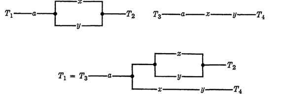
FIG. 1-1. Two 2-terminal circuits and a combined circuit.
(n + 1)-terminal circuit with terminals T0, T1, ... , Tn . where the function f2 represents the circuit connecting T0 to Ti for each i = 1, 2, . . . , n. We will assume that the possible closed paths between Ti and Tj, i ≠0, j ≠0, will cause no complications in the application of the circuit, and we will ignore the functions representing all such circuits.
This problem is, of course, a severe simplification of the more general problem of design in which each of the possible circuits is to have specified properties. The problem is still sufficiently general to have considerable value, and has the advantage of being easy to solve. In fact, the problem consists solely of examining the functions for common factors. Any such factors indicate portions of the circuits which may be shared.
If the functions involved are given explicitly, one may factor by trial and error in the attempt to find common factors, or each function may be placed in conjunctive normal form, from which common factors may be determined by inspection.
EXAMPLE 1. Design a 4-terminal circuit to realize the following three functions, using common switches wherever possible:
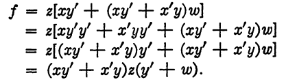
f = x y'z + (xy' + x'y)zw,
g = xy'zw' + x'yz w',
h = x'y + (xy' + x 'y) (z +w').
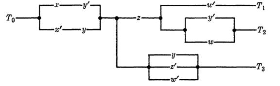
FIGURE 1-2
Solution. Since g can be most easily factored, we begin by writing it in the form
g = (xy' + x'y)zw'.
Examining f and h for possible factors in common with g, we find
Similarly,

Hence the required circuit is that of Fig. 1-2, where f = f02, g = f01, and h = f03.
If the functions are not given, but the properties are specified by a table as in Section (Design of circuits from given properties), the best procedure is to first write each function in conjunctive normal form. Common factors may be found either from the table or from the functions. The circuit is then drawn in such a way as to make the best possible use of common factors.
EXAMPLE 2. Construct a 4-terminal circuit to realize the functions f, g, and h, with properties given by Table 1-1.
TABLE 1-1
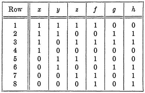
Solution. First, each function is written in conjunctive normal form:
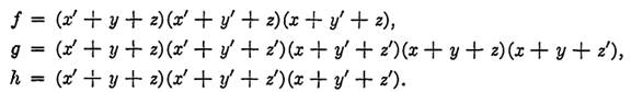
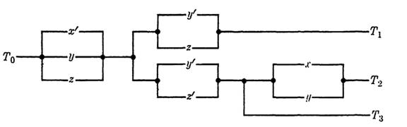
FIGURE 1-3
The common factors are noted and are indicated below with vertical lines. Simplifications are made where possible.

The final circuit is shown in Fig. 1-3, where f = ,f01. g = f02, and h = f03-In addition to cases in which the functions have common factors, there are certain other cases in which sharing of switches is possible. These cases will be easier to discuss in connection with the use of special types of switches called transfer contacts. We will postpone this discussion until the next chapter.
 الاكثر قراءة في الجبر البولياني
 اخر الاخبار
اخبار العتبة العباسية المقدسة

الآخبار الصحية


مواضيع ذات صلة
 قسم الشؤون الفكرية يصدر كتاباً يوثق تاريخ السدانة في العتبة العباسية المقدسة
 "المهمة".. إصدار قصصي يوثّق القصص الفائزة في مسابقة فتوى الدفاع المقدسة للقصة القصيرة
 (نوافذ).. إصدار أدبي يوثق القصص الفائزة في مسابقة الإمام العسكري (عليه السلام)