
تاريخ الفيزياء

علماء الفيزياء


الفيزياء الكلاسيكية

الميكانيك

الديناميكا الحرارية


الكهربائية والمغناطيسية

الكهربائية

المغناطيسية

الكهرومغناطيسية


علم البصريات

تاريخ علم البصريات

الضوء

مواضيع عامة في علم البصريات

الصوت


الفيزياء الحديثة


النظرية النسبية

النظرية النسبية الخاصة

النظرية النسبية العامة

مواضيع عامة في النظرية النسبية

ميكانيكا الكم

الفيزياء الذرية

الفيزياء الجزيئية


الفيزياء النووية

مواضيع عامة في الفيزياء النووية

النشاط الاشعاعي


فيزياء الحالة الصلبة

الموصلات

أشباه الموصلات

العوازل

مواضيع عامة في الفيزياء الصلبة

فيزياء الجوامد


الليزر

أنواع الليزر

بعض تطبيقات الليزر

مواضيع عامة في الليزر


علم الفلك

تاريخ وعلماء علم الفلك

الثقوب السوداء


المجموعة الشمسية

الشمس

كوكب عطارد

كوكب الزهرة

كوكب الأرض

كوكب المريخ

كوكب المشتري

كوكب زحل

كوكب أورانوس

كوكب نبتون

كوكب بلوتو

القمر

كواكب ومواضيع اخرى

مواضيع عامة في علم الفلك

النجوم

البلازما

الألكترونيات

خواص المادة


الطاقة البديلة

الطاقة الشمسية

مواضيع عامة في الطاقة البديلة

المد والجزر

فيزياء الجسيمات


الفيزياء والعلوم الأخرى

الفيزياء الكيميائية

الفيزياء الرياضية

الفيزياء الحيوية

الفيزياء العامة


مواضيع عامة في الفيزياء

تجارب فيزيائية

مصطلحات وتعاريف فيزيائية

وحدات القياس الفيزيائية

طرائف الفيزياء

مواضيع اخرى
Electrical resonance
المؤلف:
Richard Feynman, Robert Leighton and Matthew Sands
المصدر:
The Feynman Lectures on Physics
الجزء والصفحة:
Volume I, Chapter 23
2024-03-13
1373
The simplest and broadest technical applications of resonance are in electricity. In the electrical world there are a number of objects which can be connected to make electric circuits. These passive circuit elements, as they are often called, are of three main types, although each one has a little bit of the other two mixed in. Before describing them in greater detail, let us note that the whole idea of our mechanical oscillator being a mass on the end of a spring is only an approximation. All the mass is not actually at the “mass”; some of the mass is in the inertia of the spring. Similarly, all of the spring is not at the “spring”; the mass itself has a little elasticity, and although it may appear so, it is not absolutely rigid, and as it goes up and down, it flexes ever so slightly under the action of the spring pulling it. The same thing is true in electricity. There is an approximation in which we can lump things into “circuit elements” which are assumed to have pure, ideal characteristics. It is not the proper time to discuss that approximation here, we shall simply assume that it is true in the circumstances.
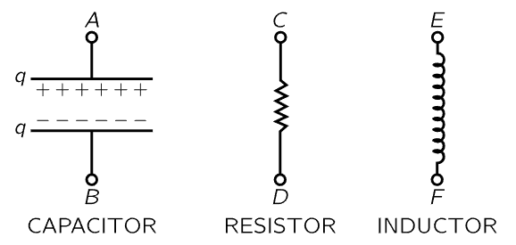
Fig. 23–4. The three passive circuit elements.
The three main kinds of circuit elements are the following. The first is called a capacitor (Fig. 23–4); an example is two plane metallic plates spaced a very small distance apart by an insulating material. When the plates are charged there is a certain voltage difference, that is, a certain difference in potential, between them. The same difference of potential appears between the terminals A and B, because if there were any difference along the connecting wire, electricity would flow right away. So, there is a certain voltage difference V between the plates if there is a certain electric charge +q and −q on them, respectively. Between the plates there will be a certain electric field; we have even found a formula for it (Chapters 13 and 14):

where d is the spacing and A is the area of the plates. Note that the potential difference is a linear function of the charge. If we do not have parallel plates, but insulated electrodes which are of any other shape, the difference in potential is still precisely proportional to the charge, but the constant of proportionality may not be so easy to compute. However, all we need to know is that the potential difference across a capacitor is proportional to the charge: V=q/C; the proportionality constant is 1/C, where C is the capacitance of the object.
The second kind of circuit element is called a resistor; it offers resistance to the flow of electrical current. It turns out that metallic wires and many other substances resist the flow of electricity in this manner: if there is a voltage difference across a piece of some substance, there exists an electric current I=dq/dt that is proportional to the electric voltage difference:

The proportionality coefficient is called the resistance R. This relationship may already be familiar to you; it is Ohm’s law.
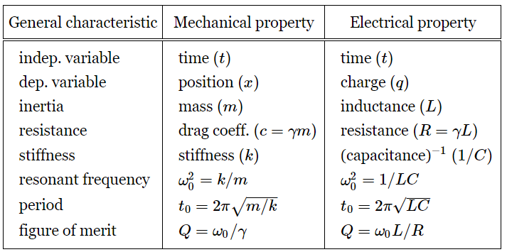
If we think of the charge q on a capacitor as being analogous to the displacement x of a mechanical system, we see that the current, I=dq/dt, is analogous to velocity, 1/C is analogous to a spring constant k, and R is analogous to the resistive coefficient c=mγ in Eq. (23.6). Now it is very interesting that there exists another circuit element which is the analog of mass! This is a coil which builds up a magnetic field within itself when there is a current in it. A changing magnetic field develops in the coil a voltage that is proportional to dI/dt (this is how a transformer works, in fact). The magnetic field is proportional to a current, and the induced voltage (so-called) in such a coil is proportional to the rate of change of the current:

The coefficient L is the self-inductance, and is analogous to the mass in a mechanical oscillating circuit.
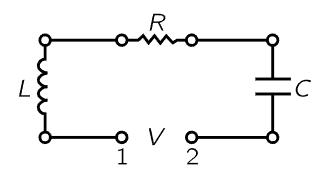
Fig. 23–5. An oscillatory electrical circuit with resistance, inductance, and capacitance.
Suppose we make a circuit in which we have connected the three circuit elements in series (Fig. 23–5); then the voltage across the whole thing from 1 to 2 is the work done in carrying a charge through, and it consists of the sum of several pieces: across the inductor, VL=L d2q/dt2; across the resistance, VR=R dq/dt; across the capacitor, VC=q/C. The sum of these is equal to the applied voltage, V:

Now we see that this equation is exactly the same as the mechanical equation (23.6), and of course it can be solved in exactly the same manner. We suppose that V(t) is oscillatory: we are driving the circuit with a generator with a pure sine wave oscillation. Then we can write our V(t) as a complex  with the understanding that it must be ultimately multiplied by eiωt, and the real part taken in order to find the true V. Likewise, the charge q can thus be analyzed, and then in exactly the same manner as in Eq. (23.8) we write the corresponding equation: the second derivative of q is (iω)2q; the first derivative is (iω)q. Thus Eq. (23.17) translates to
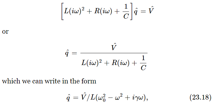
where ω20=1/LC and γ=R/L. It is exactly the same denominator as we had in the mechanical case, with exactly the same resonance properties! The correspondence between the electrical and mechanical cases is outlined in Table 23–1.
Table 23–1
We must mention a small technical point. In the electrical literature, a different notation is used. (From one field to another, the subject is not really any different, but the way of writing the notations is often different.) First, j is commonly used instead of i in electrical engineering, to denote √−1. (After all, i must be the current!) Also, the engineers would rather have a relationship between  and
and  than between
  and
and  , just because they are more used to it that way. Thus, since I=dq/dt=iωq, we can just substitute
  for
for  and get

Another way is to rewrite Eq. (23.17), so that it looks more familiar; one often sees it written this way:

At any rate, we find the relation (23.19) between voltage  and current
  which is just the same as (23.18) except divided by iω, and that produces Eq. (23.19). The quantity R+iωL+1/iωC is a complex number, and is used so much in electrical engineering that it has a name: it is called the complex impedance,
  . Thus, we can write
  . The reason that the engineers like to do this is that they learned something when they were young: V=RI for resistances, when they only knew about resistances and dc. Now they have become more educated and have ac circuits, so they want the equation to look the same. Thus, they write
  , the only difference being that the resistance is replaced by a more complicated thing, a complex quantity. So, they insist that they cannot use what everyone else in the world uses for imaginary numbers, they have to use a j for that; it is a miracle that they did not insist also that the letter Z be an R! (Then they get into trouble when they talk about current densities, for which they also use j. The difficulties of science are to a large extent the difficulties of notations, the units, and all the other artificialities which are invented by man, not by nature.)
 الاكثر قراءة في الصوت
 اخر الاخبار
اخبار العتبة العباسية المقدسة

الآخبار الصحية


 (نوافذ).. إصدار أدبي يوثق القصص الفائزة في مسابقة الإمام العسكري (عليه السلام)
 قسم الشؤون الفكرية يصدر مجموعة قصصية بعنوان (قلوب بلا مأوى)
 قسم الشؤون الفكرية يصدر مجموعة قصصية بعنوان (قلوب بلا مأوى)


