
علم الكيمياء

تاريخ الكيمياء والعلماء المشاهير

التحاضير والتجارب الكيميائية

المخاطر والوقاية في الكيمياء

اخرى

مقالات متنوعة في علم الكيمياء

كيمياء عامة


الكيمياء التحليلية

مواضيع عامة في الكيمياء التحليلية

التحليل النوعي والكمي

التحليل الآلي (الطيفي)

طرق الفصل والتنقية


الكيمياء الحياتية

مواضيع عامة في الكيمياء الحياتية

الكاربوهيدرات

الاحماض الامينية والبروتينات

الانزيمات

الدهون

الاحماض النووية

الفيتامينات والمرافقات الانزيمية

الهرمونات


الكيمياء العضوية

مواضيع عامة في الكيمياء العضوية

الهايدروكاربونات

المركبات الوسطية وميكانيكيات التفاعلات العضوية

التشخيص العضوي

تجارب وتفاعلات في الكيمياء العضوية


الكيمياء الفيزيائية

مواضيع عامة في الكيمياء الفيزيائية

الكيمياء الحرارية

حركية التفاعلات الكيميائية

الكيمياء الكهربائية


الكيمياء اللاعضوية

مواضيع عامة في الكيمياء اللاعضوية

الجدول الدوري وخواص العناصر

نظريات التآصر الكيميائي

كيمياء العناصر الانتقالية ومركباتها المعقدة


مواضيع اخرى في الكيمياء

كيمياء النانو

الكيمياء السريرية

الكيمياء الطبية والدوائية

كيمياء الاغذية والنواتج الطبيعية

الكيمياء الجنائية


الكيمياء الصناعية

البترو كيمياويات

الكيمياء الخضراء

كيمياء البيئة

كيمياء البوليمرات

مواضيع عامة في الكيمياء الصناعية

الكيمياء الاشعاعية والنووية
Wavelength Selection : Non-dispersive Elements
المؤلف:
LibreTexts Project
المصدر:
................
الجزء والصفحة:
.................
29-3-2020
1629
Wavelength Selection : Non-dispersive Elements
There are three methods of narrowing the incident electromagnetic radiation down to the desired wavelength: dispersive or non-dispersive.
Non-dispersive Elements
Wavelength selection elements are non-dispersive materials that filter out the unwanted ranges of wavelengths from the incident light source, thereby allowing only a certain range of wavelengths to pass through. For example, UV filters (as used on cameras) work by absorbing the UV radiation (100-400nm) but allowing other wavelengths to be transmitted. This type of filter is not common in modern spectrometers now that there are more precise elements available for narrowing the radiation.
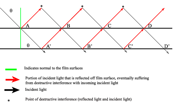
There are also interference filters that select wavelengths by causing interference effects between the incident and reflected radiation waves at each of the material boundaries in the filter. The filter has layers of a dielectric material, semitransparent metallic films, and glass; the incident light is partitioned according to the properties of each material as it passes through the layers (Ingle). If the light is of the proper wavelength when it encounters the second metallic film, then the reflected portion remains in phase with some of the incident light still entering that layer. This effectively isolates and enhances this particular wavelength while all others are removed via destructive interference.
One filter can be adjusted to allow various wavelengths to pass through it by manually changing the angle of the incident radiation (θ) angle:
Where d is the thickness of the dialectic material (on the order of the wavelength of interest), ? is the refractive index of the material, m is the order of interference, and ? is the passable wavelength. This shows that for a given material (constant d, ϵ, and m) changing λ results in a different θ. Note that when the incident radiation is normal (perpendicular) to the filter surface, then the transmittable wavelength is independent of the radiation angle:

Interferometers are also non-dispersive systems that use reflectors (usually mirrors) to direct the incident radiation along a specified path before being recombined and/or focused. Some systems also include a beam splitter that divides the incident beam and directs each portion along a different path before being recombined and directed to the detector. When the beams are recombined, only the radiation that is in phase when the beams recombine will be detected. All other radiation suffers destructive interference and is therefore removed from the spectrum. An interferogram is a photographic record produced by an interferometer.
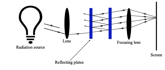
A Fabry-Perot Interferometer allows the incident radiation to be reflected back and forth between a pair of reflective plates that are separated by an air gap (Ingle). Diffuse, multi-beam incident radiation passes through a lens and is directed to the plates. Some of the radiation reflects out of the plates back towards the incident source. The remaining radiation reflects back and forth between the plates and is eventually transmitted through the pair of plates towards a focusing lens. Here all constructively interfering radiation is focused onto a screen where it creates a dark or bright spot.

Constructive interference occurs when
Where θ′ equals the angle of refraction in the air gap. This air gap can be changed to isolate particular wavelengths.
The mathematics relationships of the Fabry-Perot Interferometer relates the difference in the optical path length, Δ(OPL) , with the reflectance of the plate coatings:
Where ? is the reflectance of the plate coating.
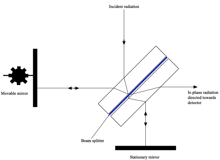
A Michelson Interferometer uses a beam splitter plate to divide the incident radiation into two beams of equal intensity. A pair of perpendicular mirrors then reflects the beams back to the splitter plate where they recombine and are directed towards the detector. One mirror is movable and the other is stationary. By moving one mirror, the path length of each beam is different, creating interference at the detector that can be measured as a function of the position of the movable mirror. At a certain distance from the splitter plate, the movable mirror causes constructive interference of the radiation at the detector such that a bright spot is detected. By varying the distance from this location, the adjustable mirror causes the radiation to fluctuate sinusoidally between being “in phase” or “out of phase” at the detector (Ingle).

The sample material to be tested is placed in the path of one of the interferometer’s beams, which changes the path length difference between the two beams. It is the change in the interference pattern at the detector between the two beams that is measured.
Other interferometers work in a similar manner, but change the angle of the mirrors rather than the position. These variations are found in the Sagnac Interferometer or the Mach-Zender Interferometer.
 الاكثر قراءة في التحليل الآلي (الطيفي)
 اخر الاخبار
اخبار العتبة العباسية المقدسة

الآخبار الصحية


 قسم الشؤون الفكرية يصدر كتاباً يوثق تاريخ السدانة في العتبة العباسية المقدسة
 "المهمة".. إصدار قصصي يوثّق القصص الفائزة في مسابقة فتوى الدفاع المقدسة للقصة القصيرة
 (نوافذ).. إصدار أدبي يوثق القصص الفائزة في مسابقة الإمام العسكري (عليه السلام)


