تاريخ الفيزياء
علماء الفيزياء


الفيزياء الكلاسيكية
الميكانيك
الديناميكا الحرارية
الكهربائية والمغناطيسية
الكهربائية
المغناطيسية
الكهرومغناطيسية
علم البصريات
تاريخ علم البصريات
الضوء
مواضيع عامة في علم البصريات
الصوت
الفيزياء الحديثة
النظرية النسبية
النظرية النسبية الخاصة
النظرية النسبية العامة
مواضيع عامة في النظرية النسبية
ميكانيكا الكم
الفيزياء الذرية
الفيزياء الجزيئية
الفيزياء النووية
مواضيع عامة في الفيزياء النووية
النشاط الاشعاعي
فيزياء الحالة الصلبة
الموصلات
أشباه الموصلات
العوازل
مواضيع عامة في الفيزياء الصلبة
فيزياء الجوامد
الليزر
أنواع الليزر
بعض تطبيقات الليزر
مواضيع عامة في الليزر
علم الفلك
تاريخ وعلماء علم الفلك
الثقوب السوداء
المجموعة الشمسية
الشمس
كوكب عطارد
كوكب الزهرة
كوكب الأرض
كوكب المريخ
كوكب المشتري
كوكب زحل
كوكب أورانوس
كوكب نبتون
كوكب بلوتو
القمر
كواكب ومواضيع اخرى
مواضيع عامة في علم الفلك
النجوم
البلازما
الألكترونيات
خواص المادة
الطاقة البديلة
الطاقة الشمسية
مواضيع عامة في الطاقة البديلة
المد والجزر
فيزياء الجسيمات
الفيزياء والعلوم الأخرى
الفيزياء الكيميائية
الفيزياء الرياضية
الفيزياء الحيوية
الفيزياء والفلسفة
الفيزياء العامة
مواضيع عامة في الفيزياء
تجارب فيزيائية
مصطلحات وتعاريف فيزيائية
وحدات القياس الفيزيائية
طرائف الفيزياء
مواضيع اخرى

AC circuits
 المؤلف:
Richard Fitzpatrick
المؤلف:
Richard Fitzpatrick
 المصدر:
Classical Electromagnetism
المصدر:
Classical Electromagnetism
 الجزء والصفحة:
p 216
الجزء والصفحة:
p 216
 9-1-2017
 4138
4138


+
-
20
AC circuits
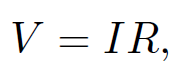
Alternating current (AC) circuits are made up of e.m.f. sources and three different types of passive element; resistors, inductors, and capacitors, Resistors satisfy Ohm's law:
 (1.1)
(1.1)
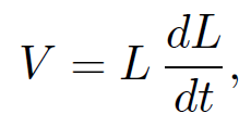
where R is the resistance, I is the current flowing through the resistor, and V is the voltage drop across the resistor (in the direction in which the current flows). Inductors satisfy
 (1.2)
(1.2)
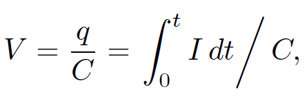
where L is the inductance. Finally, capacitors obey
 (1.3)
(1.3)
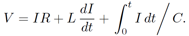
where C is the capacitance, q is the charge stored on the plate with the more positive potential, and I = 0 for t < 0. Note that any passive component of a real electrical circuit can always be represented as a combination of ideal resistors, inductors, and capacitors. Let us consider the classic LCR circuit, which consists of an inductor L, a capacitor C, and a resistor R, all connected in series with an e.m.f. source V . The circuit equation is obtained by setting the input voltage V equal to the sum of the voltage drops across the three passive elements in the circuit. Thus,
 (1.4)
(1.4)
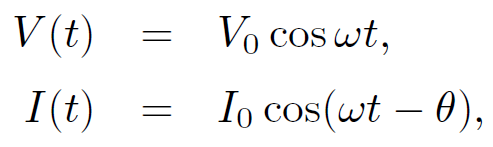
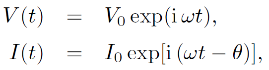
This is an integro-differential equation which, in general, is quite tricky to solve. Suppose, however, that both the voltage and the current oscillate at some angular frequency  , so that
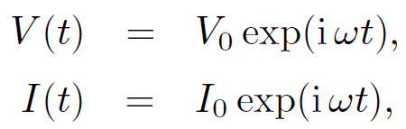 (1.5)
(1.5)
where the physical solution is understood to be the real part of the above expressions. The assumed behaviour of the voltage and current is clearly relevant to electrical circuits powered by the mains voltage (which oscillates at 60 hertz). Equations (1.4) and (1.5) yield
 (1.6)
(1.6)
giving
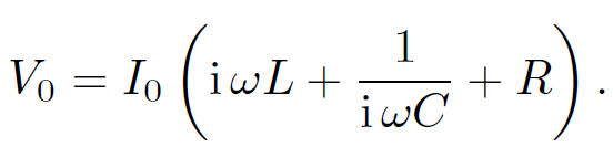 (1.7)
(1.7)
It is helpful to define the ''impedance" of the circuit;
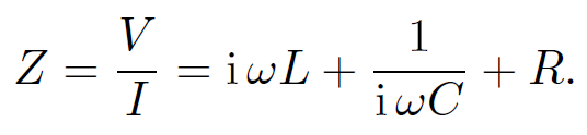 (1.8)
(1.8)
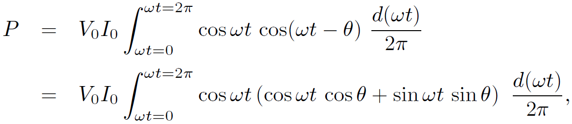
Impedance is a generalization of the concept of resistance. In general, the impedance of an AC circuit is a complex quantity. The average power output of the e.m.f. source is
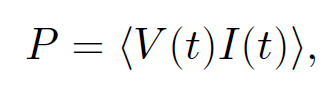 (1.9)
(1.9)
where the average is taken over one period of the oscillation. Let us, first of all, calculate the power using real (rather than complex) voltages and currents. We can write
 (1.10)
where θ is the phase lag of the current with respect to the voltage. It follows that
 (1.11)
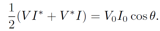
giving
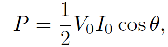 (1.12)
since  = 0 and
  = 1/2. In complex representation, the voltage and the current are written
 (1.13)
where I0 and V0 are assumed to be real quantities. Note that
 (1.14)
It follows that
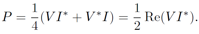 (1.15)
Making use of Eq. (1.8), we find that
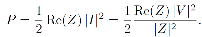 (1.16)
Note that power dissipation is associated with the real part of the impedance. For the special case of an LCR circuit,
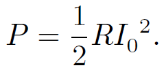 (1.17)
It is clear that only the resistor dissipates energy in this circuit. The inductor and the capacitor both store energy, but they eventually return it to the circuit without dissipation. According to Eq. (1.8), the amplitude of the current which flows in an LCR circuit for a given amplitude of the input voltage is given by
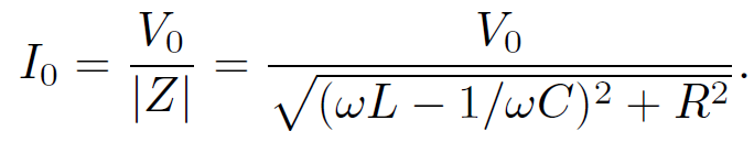 (1.18)
The response of the circuit is clearly resonant, peaking at  , and preaching
  of the peak value at
 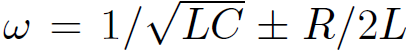 (assuming that R <<
  ). In fact, LCR circuits are used in radio tuners to filter out signals whose frequencies fall outside a given band. The phase lag of the current with respect to the voltage is given by
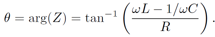 (1.19)
The phase lag varies from –π/2 for frequencies significantly below the resonant frequency, to zero at the resonant frequency( ), to π/2 for frequencies significantly above the resonant frequency. It is clear that in conventional AC circuits the circuit equation reduces to a simple algebraic equation, and the behaviour of the circuit is summed up by the impedance Z. The real part of Z tells us the power dissipated in the circuit, the magnitude of Z gives the ratio of the peak current to the peak voltage, and the argument of Z gives the phase lag of the current with respect to the voltage.
 الاكثر قراءة في الكهربائية
 اخر الاخبار
اخبار العتبة العباسية المقدسة

الآخبار الصحية


مواضيع ذات صلة
 قسم الشؤون الفكرية يصدر كتاباً يوثق تاريخ السدانة في العتبة العباسية المقدسة
 "المهمة".. إصدار قصصي يوثّق القصص الفائزة في مسابقة فتوى الدفاع المقدسة للقصة القصيرة
 (نوافذ).. إصدار أدبي يوثق القصص الفائزة في مسابقة الإمام العسكري (عليه السلام)